Schematic & Assembly
Click to enlarge the images:


This is a relatively simple project, with only 3 main components and just a handful of wired connections. For me, this made more sense to power through an external supply because it is meant to be active 24/7, though the NeoPixel is set to turn off after hours, the Pi and OLED stay running so I used a barrel jack and a universal power “wall wart”.
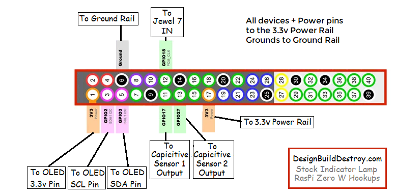
Keep in mind the Raspberry Pi is a 3.3v IO device, so we are powering ALL of this circuit with the universal power supply set to 3v, it’s output actually measures 3.4v which is perfect for the Pi and the peripherals. The capacitive touch sensors are really the issue if powering with 5v their output signal HIGH will be closer to 5v and that will no doubt fry the GPIO pins of the Pi.
The NeoPixel doesn’t seem to have any issue with the 3.4v power supply and they are still VERY bright in sunny room. In fact any shot of it in the video is dimmed down because my camera adjusted for the brightness, the room is actually brightly lit.
I find it easier to solder up a couple strips of header pins to small piece of breadboard and use them as positive and ground rails to have a central point to connect all the power lines too, and then solder the capacitor across the two rows whichever side the negative marking of your cap points to will be your ground rail the other positive ~3.3v
The Enclosure
Now this is a matter of preference. I spent some time designing the parts in Solid Works and 3D Printed them. But really you could put this into any enclosure you like. The boards are so small and being modular it makes it easy to fit into anything you have laying around.
The top in Natural PLA which is not see through at all but translucent enough that with a bright board like the Jewel 7 it really glows bright even in the day light. The bottom is just white PLA and has a lip where the dome top sits on to.
Note: On the actual STL the original idea was to have the OLED fit up into it’s position, but I found that I just could not get it to work after a couple attempts to redesign it. So I ended up just snipping off the top rail where the OLED goes and used a Dremel to fine tune things to allow the OLED to fit.
Getting Everything in Place
Hot Glue is a makers best friend! But go easy on it, you only need a few dabs to hold parts in place. Wrapping up the wires to keep them neat and fitting in well was done with a “twisty tie”, bundle them up and wrap the twisty tie around them to keep them together.
The Raspberry Pi Zero sits in front of the power board it is the only thing NOT glued in place. It’s situated in this particular enclosure in a way that if the OLED connector is removed the PI can be pulled out without much fuss if you needed to yank it it out.
Once all the main components are in their place, I simply used a craft stick (aka Popsicle stick) cut down to size and hot glued it across the center of the top of the base. Fit the stick on the inside of the base not across the top so that it doesn’t interfere with the dome when it is placed down. The Jewel 7 just a dab of hot glue on the center of the stick and press the Jewel down in place and we’re done!